It was summer in Dalarna. I was browsing Blocket, looking to flip something, when I found a late 90s Volvo S80, a first generation P2 platform, sitting dead on a driveway outside Sveg. The seller knew what was wrong. The ECU box had burned, literally melted. He had been to a dealer who quoted him north of 20 000 SEK and told him the car was essentially too modern for anyone without factory diagnostic equipment to touch. Too many computers. Too integrated. A layman's nightmare.
He wanted 1500 SEK for it. I said yes before he finished the sentence.
I said yes because I had looked at the board through the access panel and the EEPROM looked intact. Everything else could be a donor problem. The EEPROM was the soul of the thing, the calibration data, the immobiliser pairing, the accumulated learned values the ECU builds up over the life of the car. If I could get that data off the dead board and onto a functional one, the car would think it had never left.
The Platform
The first generation S80 launched in 1998 on Volvo's P2 platform, shared later with the S60, V70 and XC90. Depending on engine variant it ran either a Bosch Motronic or a Fenix engine management system. These were not the deeply integrated CAN-saturated architectures of modern vehicles. Some variants had rudimentary CAN between certain modules, others communicated over proprietary Volvo serial protocols entirely. The idea that this car required factory tooling to diagnose was largely fiction. It required someone willing to look at what was actually there.
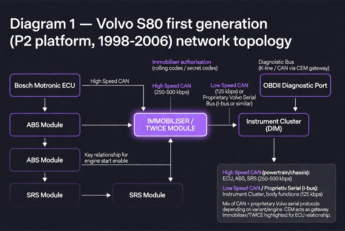
Fig. 1 — Volvo S80 first generation (P2 platform) network topology. The TWICE immobiliser module is central to the authentication chain.
The ECU in question was a Bosch unit. The fried board was visually obvious once you had it out, blackened and warped around the power section. What mattered was what survived.
The 93C86
The EEPROM on this board was a 93C86. This is worth understanding properly because it is not the chip most people reach for when they think about automotive EEPROM work.
The 93 series is a Microwire device. Microwire is a 3-wire synchronous serial protocol developed by National Semiconductor, a subset of what later became standardised as SPI but with meaningful differences in implementation. The signals are CS, SK (clock) and DI/DO (data in and out, sometimes combined as a single bidirectional line depending on the variant). The instruction set includes READ, WRITE, ERASE, EWEN (write enable) and EWDS (write disable), and crucially the chip requires an explicit write enable sequence before it will accept any write operation. Forget this and you will spend time wondering why your writes are silently failing.
The 93C86 specifically is organised as either 1024 x 8 bits or 512 x 16 bits depending on the ORG pin state, giving you 1KB or 2KB of storage. On automotive ECUs it typically holds immobiliser seed and key data, VIN encoding, learned adaptation values and in some configurations odometer data. This is why the EEPROM survives a fried board, it is a separate low power device that does not share the fate of the power electronics around it.
The CH341 supports Microwire but the timing requirements of the 93C86 are strict enough that software configuration matters. Default SPI mode assumptions will fail. You need to explicitly set the protocol to Microwire and verify your clock polarity. On the T61 running the extraction software I was using, this required manual configuration rather than autodetection.
The Bent Pin and the In-Circuit Extraction
The plan was to desolder the 93C86 from the fried board cleanly and work from there. That did not go well. Working with an iron rather than a hot air station, I botched it. One pin on the original chip folded. Not broken clean off, just bent enough that a standard clip connection was not going to work.
At that point I changed approach entirely. Instead of continuing to fight the desolder I left the chip where it was, still seated on the fried board, and went in with the CH341 clip directly on the chip in-circuit. The bent pin got a small wire bridge to close the connection. Everything else clipped normally.
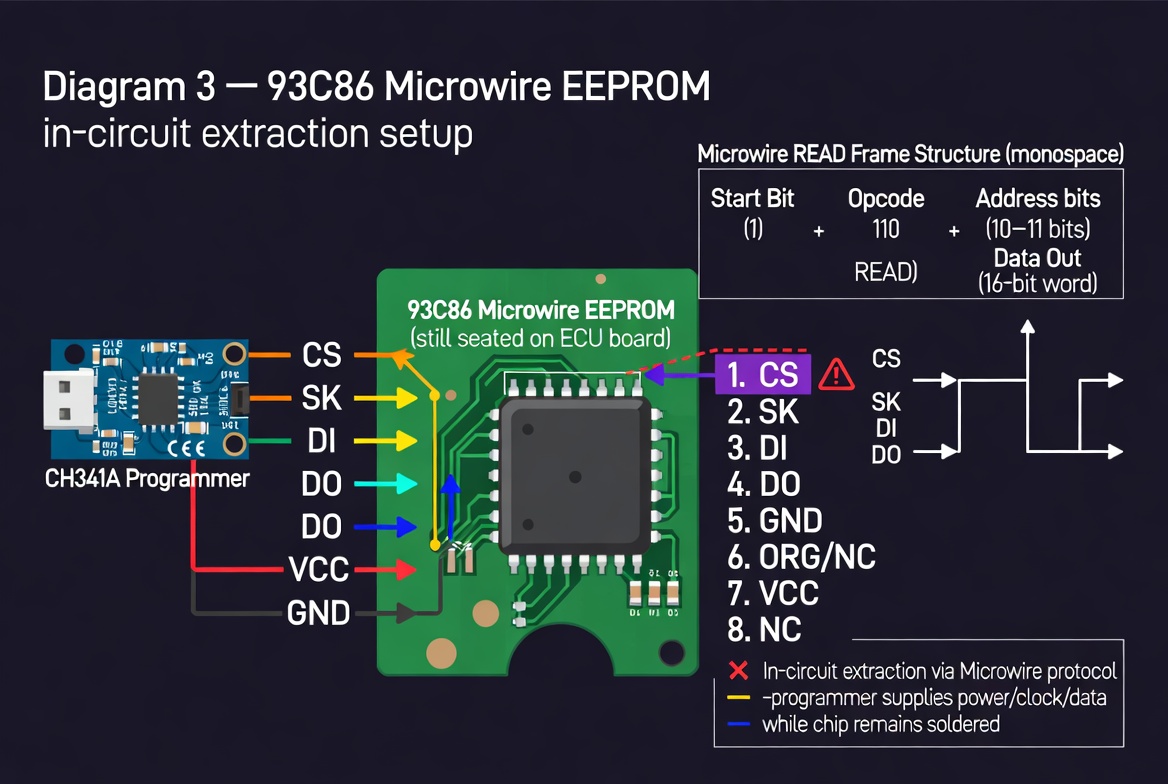
Fig. 3 — 93C86 Microwire EEPROM in-circuit extraction. Wire bridge on bent pin visible. Chip remains soldered to the board throughout.
In-circuit extraction has one significant complication. Other devices on the same bus can interfere with your read. On a dead board with no power to the surrounding circuitry this is less of a problem, but it is worth being aware of. If the board were powered and other devices were asserting the bus you would get corrupted reads. On a dead board you are usually safe.
The read came back clean. I wrote the data onto the equivalent chip on the donor board, seated it, connected everything and turned the key.
She started on the first try.
The Donor Board and the Quirks
The donor board came from a scrapyard, pulled from another S80 of a different model year. Different model year meant different software revision on the main processor. The EEPROM data I transferred contained the original car's identity, so the immobiliser pairing and calibration were correct. But the surrounding firmware had different mappings for some of the ancillary functions.
The result was a car that ran perfectly where it mattered and behaved oddly in places that did not matter. Certain button combinations triggered unintended responses. Some comfort functions mapped incorrectly. Ignition, fuel management, all lighting functions, indicators, brake lights worked exactly as they should. The car was a car. It was just not quite the car it had been from the factory, and for the price paid that was entirely acceptable.
CAN Bus as a System
The S80 I worked on was old enough that its inter-module communication was limited and partially proprietary. To understand what modern vehicles look like at the bus level and why that matters, it helps to understand CAN properly.
Controller Area Network was developed by Bosch in the mid 1980s and became the dominant automotive communication standard through the 1990s. It is a multi-master serial bus. There is no clock line and no addressing in the traditional sense. Instead every node on the bus can transmit, and every transmitted frame carries an identifier that both describes the content and determines priority. Lower numerical ID wins arbitration. A node with a higher priority message will transparently win the bus without either side needing to know about the other.
The physical layer is a differential pair, CANH and CANL. The differential signalling gives it excellent noise rejection in the electrically hostile environment of a vehicle. Standard CAN runs at speeds from 10kbps up to 1Mbps. In practice automotive implementations use 500kbps for high speed powertrain buses and 83.3kbps or 125kbps for lower speed body and comfort buses.
A CAN frame consists of a start of frame bit, an 11-bit identifier (or 29-bit in extended format), a remote transmission request bit, a data length code, up to 8 bytes of data, a CRC sequence, an acknowledge slot and an end of frame sequence. The 8 byte data payload is where everything interesting lives. A single frame might encode RPM in bytes 0 and 1, throttle position in byte 2, coolant temperature in byte 3 and so on. The mapping is manufacturer specific and often undocumented, which is what makes sniffing interesting.
Modern vehicles typically run several CAN buses at different speeds, isolated from each other by a central gateway module. The powertrain bus carries engine and transmission data. The comfort bus carries body electronics, windows, lighting, climate. A third bus often handles infotainment and instrumentation. The gateway controls what crosses between them and in what direction.
The Mercedes W209 and Bus Sniffing in Practice
A few years after the Volvo I had a Mercedes CLK W209 from 2004. This was a properly modern CAN implementation. Two buses, the high speed powertrain bus at 500kbps and the interior comfort bus running slower, connected through a gateway in the instrument cluster area.
I ran a sniffer on the interior bus permanently for a period. The instrument cluster on the W209 sits on this bus and receives frames from the powertrain bus via the gateway, rebroadcast in the interior bus format. Speed, RPM, coolant temperature, fuel level, all of it broadcasts continuously as standard frames at fixed intervals. Once you know which frame IDs correspond to which signals the data is simply there, readable by anything on the bus.
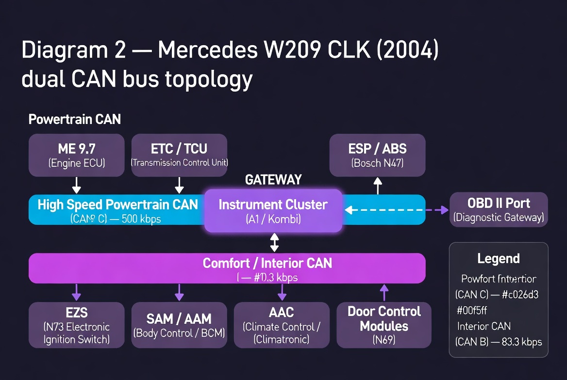
Fig. 2 — Mercedes W209 CLK (2004) dual CAN bus topology. Instrument cluster acts as gateway between powertrain and comfort buses.
The project I wanted to build was a custom digital display sourcing data directly from the bus rather than from the analogue cluster. No dependency on the factory gauges. Custom rendering, animations, layout entirely under my control. The CLK was already tuned well beyond factory specification and any further meaningful performance improvement would have required hardware changes at the engine and drivetrain level. The interesting work was in the software and the bus.
Sniffing CAN in practice requires relatively modest hardware. A USB to CAN adapter based on the MCP2515 or similar will get you onto the bus. On Linux, SocketCAN provides a clean kernel-level interface. Candump captures raw frames. Python-can gives you a scripting layer. The workflow is straightforward: capture a baseline of frames with the car at rest, then introduce a stimulus, operate a control, change a parameter, and look for frames that change in response. Repeat until you have mapped the signals you care about.
The harder part is signal decoding. Manufacturers do not publish their CAN databases publicly for obvious reasons. Some signals are straightforward, a two byte big-endian integer for RPM with a known scaling factor. Others are packed into individual bits across multiple bytes with offsets and scaling that require reverse engineering. Databases for popular platforms leak into the community over time, through open source projects like OpenDBC and through the work of people who have done the patient frame-by-frame analysis.
ECU Mapping and Manufacturer Restrictions
The tuning work I was exposed to through a friend who worked professionally with remapping gave me a different perspective on what the ECU actually contains and what manufacturers deliberately limit.
Modern engine ECUs are not simple fuel and ignition controllers. They contain elaborate maps, multidimensional lookup tables indexed by RPM, load, temperature, gear position and dozens of other parameters. The fuelling map, the ignition timing map, the boost pressure map on turbocharged engines, the torque limitation map, the rev limiter, the speed limiter. All of these exist as data in flash memory on the ECU. The hardware is frequently the same unit sold across multiple power variants of the same engine family, with different maps loaded to produce the different outputs that justify different price points.
This is manufacturer restriction by software on hardware that is physically capable of more. The 100kW variant and the 150kW variant of the same engine often share identical hardware. The difference is a table in flash memory.
Reading and writing ECU flash requires either an OBD interface if the manufacturer has left a flash bootloader accessible via the diagnostic port, or direct bench access to the ECU with JTAG or BDM connections to the processor. Volvo and many other manufacturers use Motorola 68xxx or PowerPC derivative processors with BDM debug interfaces. A BDM adapter gives you direct memory access regardless of any software locks the OEM has put in place.
The legality of modifications varies by jurisdiction and by whether the vehicle is used on public roads. The technical capability to make them is a separate question entirely.
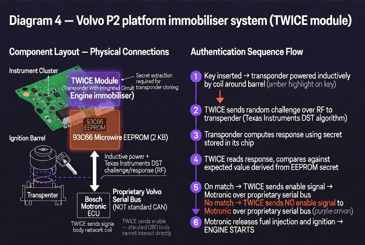
Fig. 4 — Volvo P2 TWICE module authentication sequence. Proprietary serial bus to Motronic — not accessible via standard OBD tools.
Telematics and Remote Shutdown
Modern vehicles carry a telematics unit in addition to the ECUs that actually run the drivetrain and body systems. This is a GSM or LTE connected module with its own SIM, its own processor and its own connection to the vehicle CAN bus. It exists to provide the manufacturer with telemetry, to enable remote services like stolen vehicle tracking, and in some implementations to enable remote commands including speed limitation and engine shutdown.
The remote shutdown capability works by sending an authenticated command from a backend server over the cellular network to the telematics unit. The telematics unit receives the command, validates it, and then injects CAN frames onto the bus instructing the ECU to cut fuel, limit speed or disable ignition. From the ECU's perspective it looks like any other legitimate bus message.
Reversing this is conceptually straightforward. The telematics unit is a node on the CAN bus like any other. Physically locating it, which typically means finding the cellular antenna lead and tracing it back, gives you the unit itself. From there you have several options.
The simplest is disconnection. Remove the telematics unit from the bus and it can neither receive commands nor inject frames. The tradeoff is losing any legitimate services that depend on it and potentially triggering fault codes.
More surgical is filtering. If you have mapped the CAN IDs used by the telematics unit through sniffing, you can insert a device between the telematics unit and the rest of the bus that passes normal traffic and drops frames from that specific source. A Raspberry Pi with two MCP2515 modules acting as a transparent CAN bridge with a filter rule is sufficient hardware for this.
The most complete approach is getting into the telematics unit itself. These units typically run embedded Linux or an RTOS on ARM hardware. The PCB usually has unpopulated UART pads that expose a debug console. A logic analyser will tell you the baud rate. From a shell you can examine what the unit is listening for, what it does with incoming commands and modify the behaviour at the source. Bosch and Continental units have been partially documented through community reverse engineering efforts. The attack surface is real and the research is out there for anyone willing to look.
The broader question this raises is one of ownership and control. A vehicle you have purchased contains systems that can be remotely commanded by parties other than you, without your initiation and potentially without your knowledge. Understanding the technical mechanism is the first step toward making an informed decision about whether that is acceptable.
The Moral
Do not take every word from a mechanic as gospel. Modern cars are not purely mechanical anymore. A significant portion of what makes them run is software running on hardware that is frequently more capable than the manufacturer chooses to expose. The CAN bus that ties the systems together is readable, and once you can read it you can understand it, and once you understand it you can decide what to do with that understanding.
The EU knows best, apparently. Until someone points a sniffer at the bus and reads what is actually there.
The Volvo cost fifteen hundred kronor and an afternoon. The dealer wanted twenty thousand and your trust. Know which tools to use and who to trust with them.
Tools and Resources
Everything referenced in this post has open source tooling behind it. These are the projects worth knowing.
CAN bus sniffing and analysis
SocketCAN is the right starting point on Linux. It is built into the kernel mainline and treats CAN interfaces the same as network interfaces, which means candump, cansend and Wireshark all work without additional drivers. Pair it with a cheap MCP2515-based USB adapter and you are on the bus.
python-can gives you a clean Python API over SocketCAN and a dozen other hardware interfaces. Logging, playback, filtering and message construction all in one library.
SavvyCAN is the most capable open source GUI for CAN analysis. Cross-platform, Qt-based, supports SocketCAN interfaces, DBC file import for signal decoding, and has a scripting layer.
cantools handles DBC, KCD and ARXML database files. Lets you decode raw frame bytes into named signals once you have the database for your platform.
OpenDBC is a community-maintained collection of DBC files for production vehicles. If someone has already reverse engineered the signal mappings for your platform, the database is likely here.
Caring Caribou is a CAN security exploration tool, essentially nmap for automotive networks. Useful for enumerating what is on the bus before you start mapping individual signals.
iDoka/awesome-canbus is a comprehensive curated list of CAN tools, hardware and resources. Start here if you want a full overview of the ecosystem.
EEPROM reading and writing
IMSProg is a CH341A-based programmer that supports I2C, SPI and Microwire EEPROM chips including the 93 series. Runs on Linux and macOS. The chip database covers the 93C86 and related variants.
hpaluch/ch341-spi-93lc86 is a focused project specifically documenting the 93LC86 with a CH341A, including the Microwire protocol differences from SPI that will trip you up if you assume they are the same.
MicrowireEEPROM is an Arduino library for bitbanging the Microwire protocol directly, useful if you want to build a reader without relying on the CH341.
turboat/eepromtool parses Bosch M7.5 ECU EEPROM dumps and can read and modify immobiliser state, VIN, SKC and cluster pairing data. Useful reference for understanding what the data structure looks like once you have a dump.
ECU flashing and remapping
FOME is an open source engine management firmware for aftermarket ECUs, descended from rusEFI. If you are building a custom engine management solution rather than patching OEM firmware, this is where to start.
rusEFI is the upstream project, with a large community and wide hardware support. The tuning software and firmware are both open source.
Sigrok/PulseView with the Microwire protocol decoder is the right tool for verifying your EEPROM reads at the signal level. Attach a logic analyser to the clock, data and chip select lines and decode the transaction in real time.